
 en
en
 English
  Español
  中文简体
中文简体

Content
- 1 How Blast Loads Are Characterised
- 2 Ductility and Response Criteria: The Core of Blast Design
- 3 Layout, Standoff and Structural System Selection
- 4 Analysis Methods: Hand Calculations, SDOF and Finite Element Models
- 5 Where Blast-Resistant Structures Are Actually Built
- 6 Detailing and Fabrication: Where the Design Is Won or Lost
- 7 Bringing Design, Analysis and Fabrication Together
Ask most people what a blast resistant building looks like and they will describe a fortress: thick walls, tiny windows, no give at all. In practice, the design and analysis of blast resistant structures works almost the opposite way. A structure built to resist an explosion is usually one designed to bend, yielding and absorbing energy in milliseconds so that the frame stays standing and the people inside get out.
Across three decades of fabricating heavy steel for refineries, power plants, ports and industrial plants, we have seen how often the design phase and the fabrication phase drift apart on this subject. A ductile detail agreed in a model can quietly become a rigid, brittle weld once it reaches the shop. This article covers both halves of the topic: how blast loads are characterised, how they are analysed, and what has to happen in detailing and fabrication for that analysis to mean anything on site.
How Blast Loads Are Characterised
An explosion delivers its energy in a handful of milliseconds. Pressure rises almost instantly to a peak, then decays back toward ambient, often followed by a negative phase that pulls the structure the other way. Nothing about this resembles the gravity and wind loads most structures are proportioned for, which is why blast engineering begins with loading rather than with member sizes.
Two quantities drive almost every calculation: peak reflected pressure and impulse. Reflected pressure is what the face of the building actually feels, and at normal incidence it can be several times the side-on pressure of the wave. Impulse, the area under the pressure-time curve, determines how much kinetic energy the structure has to absorb. A small charge very close to a column and a much larger charge further away can produce the same impulse at very different pressures, and the structure will not respond the same way to both.
Design normally starts from a threat definition: a charge weight and a standoff distance, converted into a scaled distance using the cube root of the charge weight. References such as UFC 3-340-02, FEMA 427 and 428, ASCE/SEI 59 and Eurocode 1 Part 1-7 then supply pressures, impulses and response criteria. The assumptions underneath those numbers are what matter most:
- Charge weight, its TNT equivalence and the assumed point of detonation
- Standoff distance and the scaled distance derived from it
- Reflected pressure, arrival time, positive phase duration and impulse
- Angle of incidence, wave clearing and shielding from nearby structures
- Confinement, venting and whether the event occurs inside or outside the envelope
Ductility and Response Criteria: The Core of Blast Design
Why blast design leans so heavily on ductility is simple arithmetic. Blast durations are far shorter than the natural period of most components, so a structure cannot respond to the full peak pressure, yet the energy still has to go somewhere. In a brittle material it goes into fracture. In a ductile one it goes into permanent deformation, and the structure survives.
Structural steel suits this behaviour exceptionally well. At the strain rates typical of a blast, roughly 100 to 10,000 per second, its apparent yield strength rises, an effect captured through dynamic increase factors in the design codes. More importantly, steel continues to strain-harden well past yield, so a member keeps carrying load while it deforms. Connections that rotate without fracturing allow beams to develop catenary action, and a composite floor slab can act as a tying diaphragm that holds the frame together when a column is lost.
Performance is normally judged against defined damage levels, from superficial through moderate and heavy to hazardous, with response expressed as a support rotation or ductility ratio rather than a stress. Structures are routinely designed to accept heavy damage; occupied buildings are usually held to something stricter. Fixing that target early, alongside the threat definition, is what keeps the analysis from becoming an open-ended exercise.
Layout, Standoff and Structural System Selection
Before a single member is sized, most of the blast resistance has already been decided by geometry. Distance is the cheapest protective measure available, and it never has to be welded. Every extra metre of standoff cuts both peak pressure and impulse sharply, so setbacks, berms and protective barriers usually deliver more protection per unit cost than additional steel.
The decisions that shape the rest of the structure are mostly about continuity and load path:
- Building layouts that keep critical functions and occupied areas away from the most exposed facades
- A structural system, ductile moment frames or adequately tied bearing-wall systems, selected for redundancy rather than for economy alone
- Ground floor columns strengthened or detailed so they can lose capacity without triggering collapse
- Light, well-tied roof systems, avoiding heavy cladding that becomes a hazard in itself
- Glazing and facade systems selected and laminated to limit flying fragments
- Avoidance of transfer structures and other details that offer no alternative load path
Analysis Methods: Hand Calculations, SDOF and Finite Element Models
Blast analysis does not have to begin with a large finite element model. Equivalent single-degree-of-freedom approaches, an idealised mass on an idealised spring, often condensed into pressure-impulse diagrams, remain valuable for early sizing, for identifying which components are critical, and for sanity-checking something more complex. They are transparent, quick to review and reasonably conservative within their assumptions.
What they cannot explain is local behaviour. They will not tell you whether a gusset plate tears, whether a connection rotates enough to develop catenary action, or how a slab redistributes load after a column is compromised. For that, nonlinear dynamic finite element analysis with an explicit solver is the usual tool. Done properly, it captures local deformation, strain-rate effects and component interaction. Done carelessly, with a coarse mesh and an elastic material model and no validation, it produces confident numbers with little connection to reality.
| Method | Typical use | Strengths | Limitations |
|---|---|---|---|
| Equivalent static and hand calculations | Early sizing and feasibility | Fast, transparent, easy to review | Ignores inertia, local response and load redistribution |
| Single-degree-of-freedom dynamic models | Component checks against code criteria | Captures dynamic response with modest effort | Idealised mass and stiffness; weak on component interaction |
| Nonlinear explicit finite element analysis | Complex geometry, connections and whole-structure response | Shows real failure modes, membrane and catenary action | Needs careful material models, mesh convergence and validation |
Where Blast-Resistant Structures Are Actually Built
Blast-resistant design is not reserved for embassies and military sites. It appears wherever an explosion is a credible event, which covers a good deal of ordinary heavy industry.
Petrochemical and Chemical Facilities
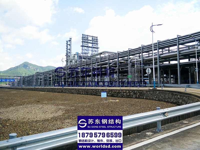
Pipe racks, process structures and control buildings in refineries and chemical plants are designed for vapour cloud explosions, and the pipe gallery itself often shapes how a blast wave travels through the plant. Spacing, bracing and connection detailing on these structures are driven as much by the explosion scenario as by the piping loads they carry.
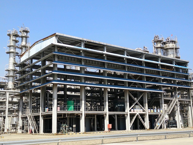 Petrochemical Pipe Gallery Heavy Steel StructureCustom heavy steel pipe gallery for refineries and petrochemical plants, supporting process piping, cable trays, and utility lines in energy projects.View Product →
Power Generation and Critical Infrastructure
Power plants and substations combine high-value equipment with a need to stay operational. Blast and security requirements influence the layout of turbine halls, transformers and switchgear buildings, and the steel frame frequently has to satisfy normal serviceability criteria while an abnormal loading case is verified separately.
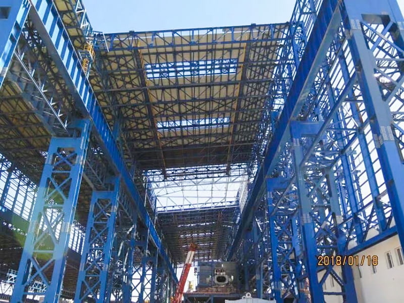 Power Plant Steel Structure Custom SolutionCustom steel structure solution for nuclear and electric power facilities, with project reference Shenhua Power Plant and inquiry options for plant owners.View Product →
Ports, Marine and Offshore Works
Ports and coastal facilities face a different mix of hazards, including impact, marine exposure and in some cases explosion. Heavy steel for cranes, quayside equipment and offshore installations demands the same qualities blast design asks for: continuity, toughness and connections that behave predictably under extreme loading.
 CNOOC Heavy Steel Structure for Public InfrastructureHeavy steel structure associated with CNOOC and public infrastructure projects, offered through an inquiry-oriented product page for further project-specific details.View Product →
Detailing and Fabrication: Where the Design Is Won or Lost
It is common to see a blast analysis that passes on paper while the fabrication drawings quietly undo it. A connection detailed with heavy stiffeners and full-penetration welds can end up stronger than the member it connects, pushing failure into a beam flange instead of a ductile hinge. A detail that restricts rotation removes the mechanism the analysis relied on. A member made from a grade with poor notch toughness may behave very differently at low temperature than the model assumed.
The remedies are practical rather than exotic. Specify steel with adequate toughness for the service temperature. Keep welds out of regions expected to hinge, or detail them so they tolerate rotation. Use continuity and doubler plates where the analysis requires them, and shear connections with clear, buildable geometry. Control weld quality through qualified procedures and non-destructive testing, and check that fabrication tolerances do not close the gaps the design depends on. Where a structure must survive a blast and the fire that frequently follows one, thermal behaviour belongs in the same conversation; the temperature at which structural steel loses strength is a useful reference point for that discussion.
Bringing Design, Analysis and Fabrication Together
Blast-resistant work rewards early coordination. The threat definition, standoff, structural system, analysis method, connection details and fabrication sequence all feed one another, and changing any of them late is expensive. The smoothest projects are those where the engineer, the detailer and the fabricator were talking well before the first drawing was issued.
That is the role we try to fill as a heavy steel fabricator. With close to thirty years in the industry, a 50,000 square metre production base, seven production lines including six robotic welding lines and a box beam line, and annual capacity of 40,000 to 50,000 tonnes, we support projects from design development through fabrication, surface treatment and site installation, and we export to overseas markets. Blast-resistant work is unforgiving, because the assumptions in a model are only as good as the welds, tolerances and material certificates that arrive on site. If you would like to see how that plays out in practice, our project portfolio shows the range of heavy structures we have delivered.